
Wolfram’s Mathematica can run on a $5 Raspberry Pi zero. While it may be painfully slow, it does open up opportunities to use Mathematica in low-power, remote-sensing applications. This blog post is a first in a series highlighting the design challenges I’ve encountered (and in some cases overcome) building Mathematica on Pi (MoP) devices. (Hey, I think I just created a new acronym.)
A MoP or a microwolf?
I’m starting to like the phrase MoP (Mathematica on Pi), so I think I’ll roll with it. Before I came up with MoP, however, I planned on calling my Raspberry-Pi-Zero-with-Mathematica sensor system microwolf, since it’s tiny. I don’t know which name will ultimately stick, so I’ll be trying them both out for a while.
So, for the microwolf MoP device (that’s probably too much), I want to have a system with the following characteristics:
- is cheap and small
- can be operated from a rechargeable battery and/or solar power
- reads sensor data numerically and graphically
- doesn’t require another computer to access data
- can be operated wirelessly
I suspect there are some additional design objectives that I haven’t thought of yet, but this will be a good foundation from which to start. Full disclosure: this post describes a not-ready-for-prime-time build. It’s a proof of concept that is working well enough for me to want to show it off, but there’s still a lot of work to do.

Hardware
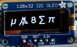
In addition to the RPi zero, I’m using a few items from Adafruit, a 128×32 OLED display which currently costs $17.50 and a BMP180 temperature and pressure sensor which will set you back $10. I also have a few breadboard-friendly pushbuttons and standard array of breadboarding supplies. I put a female header on the zero to make breadboarding a little bit easier. Add the Wifi dongle for another $12 and $5 of breadboarding components and it looks like the current build for microwolf is between $50 and $60. (I didn’t include power supply and SD card in the costs.)
Software
The RPi zero has my Kamino base installation. In addition, I had to install the python libraries for the display and sensor. Both of these packages can be found on the Adafruit website here for the sensor and here for the display. Kamino base doesn’t have I2C enabled by default, so switching this on in raspi-config should be done as well.
Design strategy
I’ve tinkered with GPIO access via Mathematica in the past. If you’re interested, I suggest you look at my github page for WiringPiLink. That project is in need of dusting off, and can probably handle I2C communication; however, the Adafruit libraries do a fine job interfacing with the sensor and display, and I can access them in Mathematica via Run and RunProcess. So this project involves:
- writing Python scripts that serve as drivers for the display and sensor;
- creating a package in Mathematica to provide high-level functions that interact with these systems;
- figuring out what I actually want to do.
Calling these python scripts multiple times is not terribly efficient and will need to be addressed at some point. I’ve played around with Python/Mathematica interactivity, so there is plenty of room for improvement. Right now, I’m interested in code simplicity and will tolerate the inefficiencies.
Where things stand
I’ve stored the code on Github if someone is interested in it (rather, for when my SD card gets corrupted and I need to restore my work). I’ll consider writing a code walkthrough at a later date, once I’ve done some refactoring. Here’s a short video of the system in action.
The video shows that Mathematica can write to the display, respond to a rudimentary interface (push buttons) and can read the sensor information. I have code to show plots, but didn’t write that into the demo. Here’s a snapshot to prove it:

Next steps
Now I’m ready to incorporate data storage and a plot of the actual data. I’ve got lab reports to grade and an exam to write; so that post will come sooner (because I’m procrastinating) or later (because I’m feeling guilty). Until then, start building your own MoP devices!